Page 1 of 23
Toshiba MOSFETs with a twist
Posted: Wed Jul 05, 2017 10:30 am
by jkeny
Richard (abaraxalito) hinted at some Toshiba MOSFETs he had found which normally were not used for audio but he had figured were perfect because of their gain & linearity for some audio applications which require these characteristics from an active device
I used one of these to build a very simple headphone buffer he designed - an SE class A design which consists of only a ccs & a mosfet (
http://www.mouser.com/ProductDetail/Tos ... ePxg%3D%3D)
The sound was glorious so I'm very interested in investigating further uses for these parts & with his help we could investigate these uses?
Richard mentioned an active I/V stage for the TDA1387 NOS DAC - it needs an active stage for best sound.
I'm interested in building this with his guidance & for the general interest of the readership here
Re: Toshiba MOSFETs with a twist
Posted: Wed Jul 05, 2017 12:25 pm
by nige2000
is there a n channel complementary part?
is that the idea
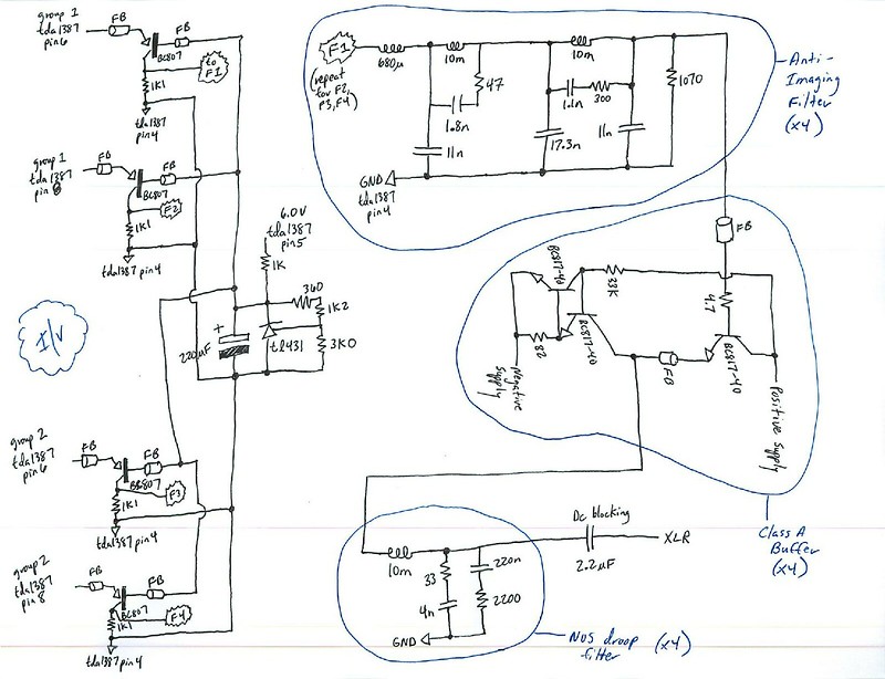
the last few experiments with signal buffers seem to provide an extra clarity or focus to the sound, bass is tauter and more resolution
the last experiment was a jfet buffer on the signal into the class a amp with a k170/j74 frontend which is supposed to be a high impedance input
but yet there still is benefit.....
its like the higher impedance signal does not have the power to drive the amp keeping the dynamic response times as short as it should be
ive some tda1387 here somewhere im up for building another
Re: Toshiba MOSFETs with a twist
Posted: Wed Jul 05, 2017 12:54 pm
by jkeny
Thanks Nige
With regard to "headbuffer"it's even simpler than that - it's basically just the same as the class A buffer in that schematic but all MOSFETS - ccs is on top & output is taken from source of MOSFET through a cap.
It's SE class A so no complimentary device needed
Here's a pic showing the size of this. This is the stereo "headbuffer", 2 channels - the green SOT23 adapter boards are 0.5" X 0.5" & each has a MOSFET mounted - 6 green boards in total - that's the buffer - the rest on the blue board are the passives on the input & output
A number of smd resistors but some through hole caps & resistors as well - it would be even smaller with all smd
https://drive.google.com/file/d/0BzRUtX ... sp=sharing
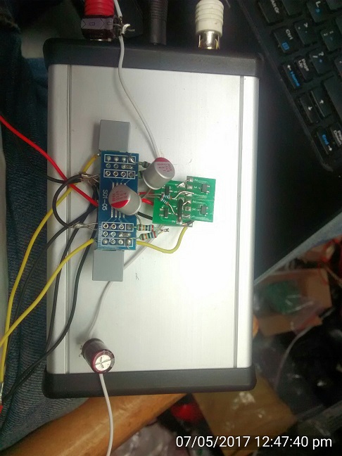
- headbuffer2.jpg (95.13 KiB) Viewed 2620 times
I'm sure suitable changes to that schematic will yield an even simpler design using these MOSFETS?
Re: Toshiba MOSFETs with a twist
Posted: Wed Jul 05, 2017 1:11 pm
by jkeny
The ccs I did was a hybrid BJT & MOSFET one which only requires 3.3 - 3.6v - so battery powering is perfect but it doesn't need clean power, it has great PSRR & hard to tell any difference between driven by battery or by Dc-DC converter
Re: Toshiba MOSFETs with a twist
Posted: Wed Jul 05, 2017 1:54 pm
by abraxalito
nige2000 wrote: ↑Wed Jul 05, 2017 12:25 pm
is there a n channel complementary part?
This one is the closest I've found to a complement -
http://www.mouser.com/ProductDetail/Tos ... rySQ%3d%3d
Its twice the voltage (40V) but otherwise quite similar in terms of transconductance.
The high transconductance (on the datasheets often called Yfs, sometimes gm) is the key feature of these MOSFETs. Its way above the gm of the much lauded (and now mostly unobtainium) Toshiba JFETs - although MOSFETs don't have the low noise of the JFETs, I've yet to notice any problem with noise in these line-level circuits.
The I/V transistors (far left) can be exchanged for the J327s in that schematic - the threshold voltage though may be a little bit higher and is certainly more variable than with bipolars. So a bit of tweaking might be needed. Nowadays I run my 1387s on 6V to get the most output swing.
As John was saying the buffer circuit in that schematic (right side) using an EF loaded by a CCS can be changed to a FET (its an NPN so use the K339) and the output transistor in the CCS to another K339. But I've learned a little since I designed that buffer, now I reckon its best to do it with a CCS to positive and a P-channel FET.
I'll post up some pics of my prototype 'hot buffer' in another post shortly....
Re: Toshiba MOSFETs with a twist
Posted: Wed Jul 05, 2017 2:10 pm
by jkeny
Cool, Richard, I'm ready to exchange the existing ccs in the headbuffer to your new 'hot buffer' whenever you post
Re: Toshiba MOSFETs with a twist
Posted: Wed Jul 05, 2017 2:26 pm
by abraxalito

- TKhot.png (13.59 KiB) Viewed 2606 times
Here's the schematic from LTspice - one quirk is the power supply is 'upside down' because its using N-channel FETs (more choices of these). Otherwise its the same basic schematic as the one John's built.
Here are a few pics of the prototype 'hot buffer' (so named because its too hot to pick up, running about 16W total dissipation). Its easily the best headphone amp I've heard, even better than ones using OPTs.
Turns out I can't upload because my files are 'too large' so I'll have to figure out a way to shrink them down. Shrunk and attached :
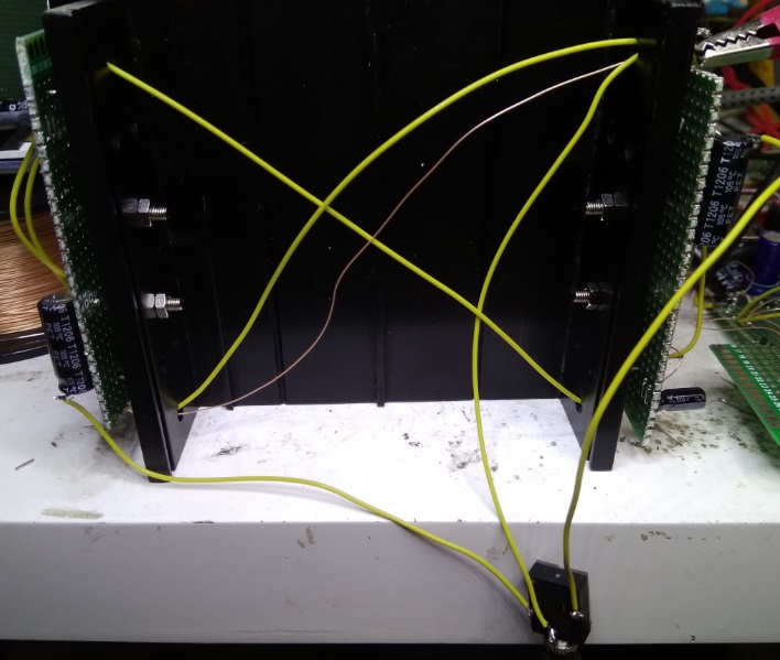
- TKhotbuff 1.jpg (104.31 KiB) Viewed 2553 times
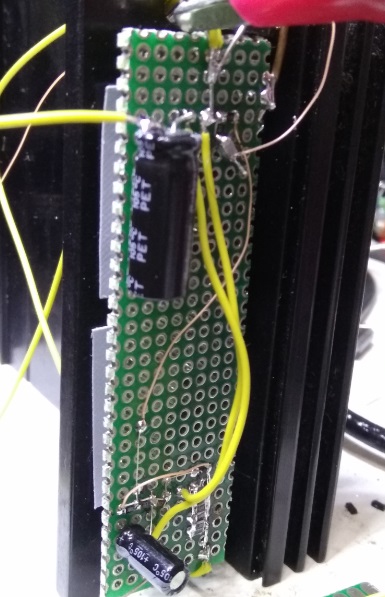
- TKhotbuff2.jpg (83.88 KiB) Viewed 2553 times
Re: Toshiba MOSFETs with a twist
Posted: Wed Jul 05, 2017 3:14 pm
by jkeny
Great - I thought the "hot buffer" was a reference to the sound :)
I need to wait for those parts to arrive to build this
I only have 47n caps of a half decent quality for the input -- they should do, right?
What size heatsink are you using?
Re: Toshiba MOSFETs with a twist
Posted: Wed Jul 05, 2017 3:41 pm
by abraxalito
Yeah I think you'll only lose a very small smidgeon of bass with 47nF in place of 100nF. You can always increase the 820k to 1.5M to compensate if you're so inclined.
The heatsink is 15*10cm with 1.5cm high fins. The FETs are mounted on two 5mm thick 'wings' at right angles to the underside. Its one I think I originally bought from Maplin over two decades ago so I doubt I could find an online equivalent. I reckon you'll need an overall thermal resistance in the region 2-3oC/W if you want the surface to be short-term touchable.
The 500mA bias really is overkill as no headphones are going to need anything close to that output current - what it buys is higher gm (hence lower output impedance, better PSRR, lower distortion) in the MOSFET.
If you're ordering heatsinks from Mouser, these look to be good value and if you put each transistor on its own one you'll be able to up the bias even more than I have :
http://www.mouser.com/ProductDetail/Ohm ... 4U4BtvA%3d
Re: Toshiba MOSFETs with a twist
Posted: Wed Jul 05, 2017 6:06 pm
by jkeny
Anybody local who's interested in headphones & wants to try this out - I've one built & cased up for sampling. it's designed for 34 ohm Superlux HD 681 headphones but will drive anything over this impedance of suitable sensitivity.
Remember it's not an amplifier, no voltage gain but nice current gain
Photos here connectors are:
- stereo phono RCA inputs
- 5V input
- 1/8" headphone output jack
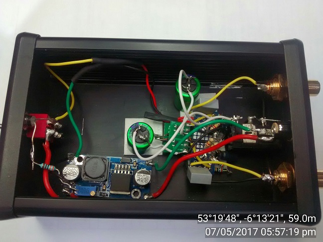
- Headbuffer cased.jpg (98.04 KiB) Viewed 2587 times
