Page 80 of 87
Re: Soekris Dam Dac
Posted: Wed Jun 13, 2018 11:29 pm
by jkeny
nige2000 wrote: ↑Wed Jun 13, 2018 11:21 pm
if i remember right it uses mosfets and ref voltage and a single ps
kinda charges like a voltage divider would
Any, circuit diagram?
It's OK, I got it
Re: Soekris Dam Dac
Posted: Wed Jun 13, 2018 11:46 pm
by nige2000
must be on my other computer, think it was slightly different to that hackaday circuit though
Re: Soekris Dam Dac
Posted: Thu Jun 14, 2018 3:48 pm
by randytsuch
John
Yeah, that hackaday was where I copied the circuit from
Here is my ltspice circuit I used for the sim.
Basically you stack the regs on top of each other, so you don't need separate ps taps like Nige did for his amp.
Adjust R1 for current you need, and maybe change Q3 and Q4 to larger devices.
Re: Soekris Dam Dac
Posted: Thu Jun 14, 2018 5:10 pm
by frd1996
The charts here:
https://hackaday.io/project/9072-open-a ... simulation
indicate charging current of 100mA.
Below he mentions charging current of 1A. If you plan bypass the cell and maintain the 1A current I say you definitely need a bigger transistor and some heat sinking.
Re: Soekris Dam Dac
Posted: Thu Jun 14, 2018 5:38 pm
by randytsuch
The design as shown was made for 200ma.
Should be enough for any dac. The transistors I used are rated for 500ma if I remember correctly, and the power supply that provided the raw power was probably less than that, so for my purposes 200ma was fine.
Maybe if you were powering an amp you would need more current, but for my purposes this is fine.
And since I have the batteries, they take care of any instantaneous demands over 200ma. As long as the average current draw for whatever you are powering is less than 200ma, this should work fine.
Note that his R1 is a smaller value than what I used. This resistor sets the current limit for the circuit.
Randy
Re: Soekris Dam Dac
Posted: Thu Jun 14, 2018 7:45 pm
by jkeny
Thanks Randy - I presume you still need a relay/switch between each battery & it's charger to isolate it or is there very little current leakage draining the batteries?
Re: Soekris Dam Dac
Posted: Thu Jun 14, 2018 8:09 pm
by randytsuch
I put a switch in, otherwise the batteries will drain.
Re: Soekris Dam Dac
Posted: Thu Jun 14, 2018 9:24 pm
by jkeny
For single LiFePo4 battery you can use charger boards based on TP5000 IC - very low back leakage & no need for switch or relay to isolate battery
Indicator Led to show CC/CV charging & fully charged - 2 Amp CC when used with small heatsink, otherwise 1-1.5Amp & 3.6V max voltage
Using some additional circuitry, chargers could be connected to multiple batteries in series
Search for them on ebay - about $2 from China
Re: Soekris Dam Dac
Posted: Thu Jun 14, 2018 11:00 pm
by nige2000
jkeny wrote: ↑Thu Jun 14, 2018 9:24 pm
For single LiFePo4 battery you can use charger boards based on TP5000 IC - very low back leakage & no need for switch or relay to isolate battery
Indicator Led to show CC/CV charging & fully charged - 2 Amp CC when used with small heatsink, otherwise 1-1.5Amp & 3.6V max voltage
Using some additional circuitry, chargers could be connected to multiple batteries in series
Search for them on ebay - about $2 from China
is that something that needs multiple ps windings for multiple cells in series to provide isolation between each charger circuit supply?
Re: Soekris Dam Dac
Posted: Sat Jun 16, 2018 12:03 am
by jkeny
nige2000 wrote: ↑Thu Jun 14, 2018 11:00 pm
jkeny wrote: ↑Thu Jun 14, 2018 9:24 pm
For single LiFePo4 battery you can use charger boards based on TP5000 IC - very low back leakage & no need for switch or relay to isolate battery
Indicator Led to show CC/CV charging & fully charged - 2 Amp CC when used with small heatsink, otherwise 1-1.5Amp & 3.6V max voltage
Using some additional circuitry, chargers could be connected to multiple batteries in series
Search for them on ebay - about $2 from China
is that something that needs multiple ps windings for multiple cells in series to provide isolation between each charger circuit supply?
Using these TP5000 a simple configuration like this could work (it's limited by the 10V max input voltage of the TP5000 stated in the datasheet although board sellers recommend 9V max) which effectively limits it to 3 batteries - maybe only 2?
These turn off when battery charge reaches 3.6V & if not powered the leakage from battery to TP5000 is very very small - so no worries about discharging battery - no need for relay or switches to isolate battery
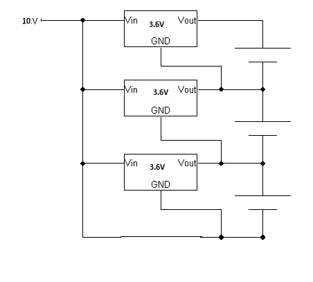
- multi-battery charging.jpg (19.22 KiB) Viewed 1956 times
These would also work & they have a 36V input max so good for 10 batteries - LTM8052 but they would need a relay or switch between each charger & battery to prevent back leakage
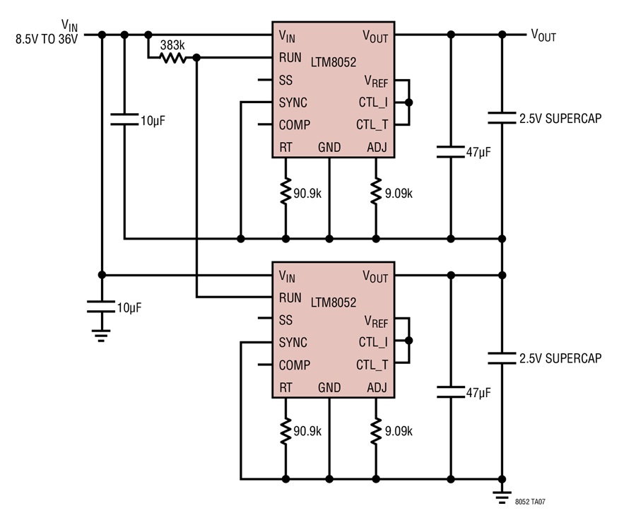
- multi-battery charging 2.jpg (76.74 KiB) Viewed 1956 times
Sorry, that only does 2.5V output - what is needed for one of these voltage regulators is one that can source & sink current - a 2-quadrant regulator