Toshiba MOSFETs with a twist

abraxalito
Posts: 230
Joined: Fri Sep 16, 2016 11:05 pm

Re: Toshiba MOSFETs with a twist

Post by abraxalito »

Its been a jolly long while since something DAC-related worked on first power up, but this one did.
DACV2.0finished.jpg
DACV2.0finished.jpg (71.58 KiB) Viewed 571 times
The string of ferrite beads is to get the right value out of the left inductor (25uH). It might be fun to build the whole filter out of bead strings like this as the attainable Q beats any commercially available inductors by a substantial margin. Maybe in a future lash up....

7thorderLC.png
7thorderLC.png (19.78 KiB) Viewed 567 times
This is what's possible with a string of three inductors (at least in LTspice). Its a text-book -92dB rejection of image products but not as steep as the two inductor version. This is designed for 2X OS.
nige2000
Posts: 4253
Joined: Thu Feb 14, 2013 10:47 am
Location: meath

Re: Toshiba MOSFETs with a twist

Post by nige2000 »

on the red board is that just the filter or gainstage and filter?
sd card player, modded soekris dac, class a lifepo4 amp or gb class a/b amp, diy open baffle speakers based on project audio mundorf trio 10's
abraxalito
Posts: 230
Joined: Fri Sep 16, 2016 11:05 pm

Re: Toshiba MOSFETs with a twist

Post by abraxalito »

The red board holds the filter (3 inductors and 3 lumps of caps per chan) followed by the I/V stage (cascoded J327s) biassed by current sources top and bottom. Then a combined buffer/NOS droop correction stage (CCS loaded J327 in a 2nd order Sallen-Key filter).
No gainstage on this - the max output is about 1VRMS which is plenty to feed into the headbuff.

Some listening done now - its the best DAC I've made to date, there's more believability particularly in the LF. Not a huge improvement but a worthwhile one. I wonder how much is due to the filter between DAC and I/V (first time I've included such a complex filter in this location) or perhaps the cascoded I/V. Anyway a very promising result indeed for such a lowly DAC chip.

The V3 will have larger Ls for lower losses (P14 gapped cores, desktop duty) but keep the rest pretty much the same.
abraxalito
Posts: 230
Joined: Fri Sep 16, 2016 11:05 pm

Re: Toshiba MOSFETs with a twist

Post by abraxalito »

Playing with another way to build this filter because the ferrite beads aren't a standard item available from international sources, just some I picked up in bulk from the local e-market. So I was looking at another way to get two inductors differing in value by about 15%.

Over on the TDK inductor product selector its possible to search for inductors on the basis of Q factor at a particular frequency, so I plugged in 20kHz and got the results ranked in order of Q (which is the opposite of lossiness in an inductor). The highest Q in the 7mm form factor is 150uH - I just happened to have some of those so I'm paralleling them up to make a much lower value (22uH as used on the V2). Paralleling inductors has the advantage that the tolerances sharpen up, on average. I found an average value (of over 20 samples) around 140uH, 7 in parallel gives me 20uH with lower losses than the single 22uH. 6 in parallel gives about 23uH. These values are a bit on the low side since all my inductors bar one were well under 150uH.

I then tripped over to Mouser to check on the prices for these 7mm puppies and found they're ridiculously expensive, even in 1000s. Here I'm paying about 10c a piece. RS comes to the rescue again though, about 28p there even for 10s.
SLF7045.jpg
SLF7045.jpg (104.84 KiB) Viewed 528 times
jkeny
Posts: 2387
Joined: Sun Jan 17, 2010 9:37 pm

Re: Toshiba MOSFETs with a twist

Post by jkeny »

Can I just ask - what final spec for the inductor you are working towards - a 22uH inductor with highest Q & lowest loss (impedance?) - form factor is not that important, is it? Or is it more to do with getting two inductors with 15% difference @ highest Q & lowest losses, the 22uH is not that critical as Caps can be adjusted in value for the filter. It doesn't seem like this is the same filter schema as posted here?:
Image

Looking at that TDK table sorted by Q (for 20KHz), I see a single inductor of 22uH with Q of 55.8 & 2.4ohm Z - is the 20% tolerance too far off i.e a range of 17.6uH to 26.4uH & the losses @ 2.4ohm, too large? Note: even though the TDK table is sorted according to Q @ 20KHz (I presume?) the values shown on the table are @ 100KHz measurement

By paralleling higher Q inductors you are trying to bring down the Z (losses?) for the same or higher Q factor - is that correct?

All these inductors are 20% tolerance so getting a 22uH (which is how critical?) even with paralleling is a bit of a guess?

On my display of the table the 100uH with 70Q & 12ohm Z has higher Q than 150uH of 67 - does this make much of a difference
www.Ciunas.biz
For Digital Audio playback that delivers WHERE the performers are on stage but more importantly WHY they are there.
abraxalito
Posts: 230
Joined: Fri Sep 16, 2016 11:05 pm

Re: Toshiba MOSFETs with a twist

Post by abraxalito »

jkeny wrote: Mon Aug 07, 2017 3:05 pm Can I just ask - what final spec for the inductor you are working towards - a 22uH inductor with highest Q & lowest loss (impedance?) - form factor is not that important, is it? Or is it more to do with getting two inductors with 15% difference @ highest Q & lowest losses, the 22uH is not that critical as Caps can be adjusted in value for the filter.
I'm not even sure myself - looking at two options, firstly a portable where size and weight are crucial and second a desktop where ultimate performance is the aim.
It doesn't seem like this is the same filter schema as posted here?:
Image
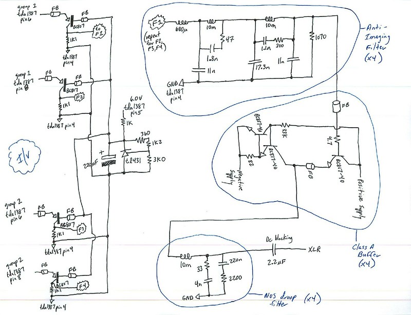
Quite right - not at all the same because this later design slots into an earlier spot in the signal chain, right after the DAC and before the I/V transistor. The earlier design puts the filter after the I/V - hence the working impedance is higher, the value of the IV resistor (in this case 1100 ohms). Such a high working impedance calls for high value inductors (10mH). But small sized high value inductors are very hard to source, hence I decided to place the filter where it could be built from low-valued Ls. Then having listened I reckon this solution sounds superior and I won't be going back to the old architecture.
Looking at that TDK table sorted by Q (for 20KHz), I see a single inductor of 22uH with Q of 55.8 & 2.4ohm Z - is the 20% tolerance too far off i.e a range of 17.6uH to 26.4uH & the losses @ 2.4ohm, too large? Note: even though the TDK table is sorted according to Q @ 20KHz (I presume?) the values shown on the table are @ 100KHz measurement
2.4ohm isn't at all consistent with a Q of 55.8. I reckon it should be below 50mohm to get to this Q. Normally Z is used to show impedance, not loss.
By paralleling higher Q inductors you are trying to bring down the Z (losses?) for the same or higher Q factor - is that correct?
I'm doing a couple of things in addition to reducing the losses slightly - getting a non-standard value and reducing the effects of tolerances.
All these inductors are 20% tolerance so getting a 22uH (which is how critical?) even with paralleling is a bit of a guess?
Yes they're 20% according to the manufacturer however for the vast majority they're closer than this. So its possible to just weed out the outliers and use the bulk of them which in this case were between 131 and 146uH - a spread of about 10%. Then when they're paralleled the tolerance reduces further. I haven't done sims to determine the degree of sensitivity of the circuit to tolerance yet.
On my display of the table the 100uH with 70Q & 12ohm Z has higher Q than 150uH of 67 - does this make much of a difference
Going down to 100uH makes it more difficult to achieve 15% difference between the two values.
jkeny
Posts: 2387
Joined: Sun Jan 17, 2010 9:37 pm

Re: Toshiba MOSFETs with a twist

Post by jkeny »

Thanks for the detailed answer
Is there a schematic for the new filter yet or waiting until you have it nailed?
Anything we can do to help - like searching for suitable inductors?
www.Ciunas.biz
For Digital Audio playback that delivers WHERE the performers are on stage but more importantly WHY they are there.
abraxalito
Posts: 230
Joined: Fri Sep 16, 2016 11:05 pm

Re: Toshiba MOSFETs with a twist

Post by abraxalito »

I'll send over the schematic for the updated filter once I'm sure it works - after building it and listening to it. The unknown is that the loading of the filter is provided by the I/V MOSFET which I don't have a model for so far. The form of it is the same as the old one with the 10mH inductors, except there's no need for an input inductor any more (shown as 680uH in the schematic you posted) nor any output load resistor (shown as 1070ohm). Whilst I designed for inductors of 25uH and 21.6uH originally, the simulator is showing that reducing them to 20uH and 23uH makes hardly any difference - slightly higher cut-off frequency.
jkeny
Posts: 2387
Joined: Sun Jan 17, 2010 9:37 pm

Re: Toshiba MOSFETs with a twist

Post by jkeny »

Great, thanks - there's no rush from me - I'm still struggling with I2C programming of DAC chip - started a new thread on it looking for help
www.Ciunas.biz
For Digital Audio playback that delivers WHERE the performers are on stage but more importantly WHY they are there.
abraxalito
Posts: 230
Joined: Fri Sep 16, 2016 11:05 pm

Re: Toshiba MOSFETs with a twist

Post by abraxalito »

I made the frequency response measurement today - shocked to find I had inadvertently engineered in a dip of about 5dB around 10kHz due to not using the right model for the J327 MOSFET. Wipes egg off face gingerly. Back to the drawing board to explore ways to get the FR flat...
Post Reply