Re: It didn't explode....... YET (aka niges amp)
Posted: Sun Aug 21, 2016 4:46 pm
OK, I think finished the layout. Nige, I sent you the DipTrace source files. Please let me know if you need anything else.
Cheers,
F
Cheers,
F
Hi-End HiFi in Ireland
https://tirnahifi.org/forum/
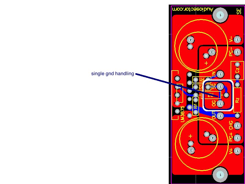
we were thinkin as the jfet buffer and lm3875 does not need a gnd connection perse just v+ and v- the battery terminal 0v will be star gnd for all (incl speaker) returns having multiple gnd connections to the amp board has the possibility of a gnd loopjkeny wrote:Some suggestions :
- keep PS grounds together & signal grounds together (input & output)
- join them together by a narrow trace or wire
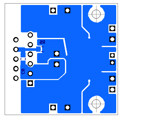
Is the blue colour in the above diagrams the bottom copper plane of a 2 layer board - mostly taken up by a ground plane?nige2000 wrote:we were thinkin as the jfet buffer and lm3875 does not need a gnd connection perse just v+ and v- the battery terminal 0v will be star gnd for all (incl speaker) returns having multiple gnd connections to the amp board has the possibility of a gnd loopjkeny wrote:Some suggestions :
- keep PS grounds together & signal grounds together (input & output)
- join them together by a narrow trace or wire
i think i see a couple of vias between all gnds on the diptrace files
batteries are pretty forgiving might all have no effect
When designing a layout, it is important to return the load ground, the output compensation ground, and the low
level (feedback and input) grounds to the circuit board common ground point through separate paths. Otherwise,
large currents flowing along a ground conductor will generate voltages on the conductor which can effectively act
as signals at the input, resulting in high frequency oscillation or excessive distortion. It is advisable to keep the
output compensation components and the 0.1 μF supply decoupling capacitors as close as possible to the
LM3875 to reduce the effects of PCB trace resistance and inductance. For the same reason, the ground return
paths should be as short as possible.
how is that possible there is no gnd pin on the lm3875 the only return surely for v+ can be v- and visa versajkeny wrote:Is the blue colour in the above diagrams the bottom copper plane of a 2 layer board - mostly taken up by a ground plane?nige2000 wrote:we were thinkin as the jfet buffer and lm3875 does not need a gnd connection perse just v+ and v- the battery terminal 0v will be star gnd for all (incl speaker) returns having multiple gnd connections to the amp board has the possibility of a gnd loopjkeny wrote:Some suggestions :
- keep PS grounds together & signal grounds together (input & output)
- join them together by a narrow trace or wire
i think i see a couple of vias between all gnds on the diptrace files
batteries are pretty forgiving might all have no effect
LM3875 is a dual supply device but that just means that both supplies return currents to ground.

keep em coming :)The datasheet has a section called "LAYOUT, GROUND LOOPS AND STABILITY"When designing a layout, it is important to return the load ground, the output compensation ground, and the low
level (feedback and input) grounds to the circuit board common ground point through separate paths. Otherwise,
large currents flowing along a ground conductor will generate voltages on the conductor which can effectively act
as signals at the input, resulting in high frequency oscillation or excessive distortion. It is advisable to keep the
output compensation components and the 0.1 μF supply decoupling capacitors as close as possible to the
LM3875 to reduce the effects of PCB trace resistance and inductance. For the same reason, the ground return
paths should be as short as possible.
Just my suggestions if you are designing a pcb!
i think i see what your on about in this picYes, it may not be important with battery supply but I would still try to follow these guidelines


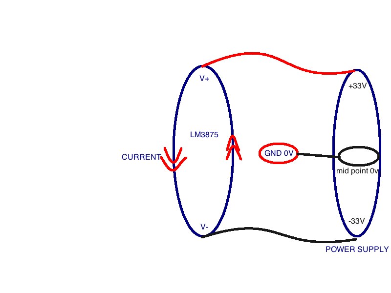
but -33 is the return for +33 that is circuit completedjkeny wrote: Edit: Nige - you can't provide +33V without having a ground return to your battery pack. Similar with -33V, +18v -18V - they all need returns to battery to complete the circuit. All these returns need to be connected at one ground point i.e they are not floating, otherwise you will get ground loop hum problems.
I'm not sure of your battery arrangements - if you are using multiple batteries in a pack & taking the midpoint as ground then that mid-point/ground is where your PS currents return to from both +33V & -33V supply - the +33V currents don't return to the -33V. If you are using one 66V battery& creating a virtual ground then that is the return point, I believe.nige2000 wrote:but -33 is the return for +33 that is circuit completedjkeny wrote: Edit: Nige - you can't provide +33V without having a ground return to your battery pack. Similar with -33V, +18v -18V - they all need returns to battery to complete the circuit. All these returns need to be connected at one ground point i.e they are not floating, otherwise you will get ground loop hum problems.
its same as using a single supply 0-66v and we use +33 (midpoint) as our gnd point at cell 0v which is connected to lm3875 pcb gnd and speaker return and chassis gnd
oh.... the battery pack is one unit 0 - 66v not two 0-33v
if you connect to any two voltages on the 20 voltage rails thats a completed circuit