Page 37 of 76
Re: It didn't explode....... YET (aka niges amp)
Posted: Mon Apr 24, 2017 10:20 pm
by nige2000


this was the way i was thinking of laying out the amp boards
all line level input switching and vol control on the inside (middle) of amp boards
the amplified signal out on the outside
hopefully providing relatively short paths but workable lengths too
any other ideas?
Re: It didn't explode....... YET (aka niges amp)
Posted: Mon Apr 24, 2017 11:04 pm
by Fran
If people still want indication leds on the front panel, I was thinking some ribbon cable could work very neatly, tucked in neatly to one side, or running down the centre along the floor.
Layout looks good and logical. We should consider arranging wiring so that the rear panel can be dropped easily to gain access to the circuit boards if any soldering etc is needed after assembly?
Re: It didn't explode....... YET (aka niges amp)
Posted: Mon Apr 24, 2017 11:56 pm
by nige2000
think we definitely need at least two leds one for mains on/charging and one for amp powered on
ill look about mounting that alu amp board mount bracket on rear panel instead of case floor tomorrow
that could mean we could provide longer power wires and then the amp section will come off with the rear panel and signal wires remain compact?
i wonder if this "piece of mind" meter would be too naf to put on the front panel?
juat to let you know all voltages are correct and right
 http://www.ebay.com/itm/Mini-LED-DC-Vol ... SwAuZX5J69
Re: It didn't explode....... YET (aka niges amp)
Posted: Tue Apr 25, 2017 9:12 am
by frd1996
Nige, Pearse, That looks fantastic. Amazing job guys!
F
Re: It didn't explode....... YET (aka niges amp)
Posted: Tue Apr 25, 2017 11:36 am
by nige2000


mounting amp boards and alu angle bracket on the back panel seems doable, however needs additional fabrication two holes need to be drilled into alu to let the third rca input in, assuming three inputs?
an additional piece of angle needed to mount the switch and pot on to
extra screw heads on the back panel
hmmn as i type i think there should be plenty of working room/access from the top with the original placement
any thoughts?
maybe mot as cramped as it seems in pics


Re: It didn't explode....... YET (aka niges amp)
Posted: Tue Apr 25, 2017 9:49 pm
by nige2000
Re: It didn't explode....... YET (aka niges amp)
Posted: Wed Apr 26, 2017 2:12 pm
by Sligolad
Nice work Nige, starting to look better than I had imagined now.
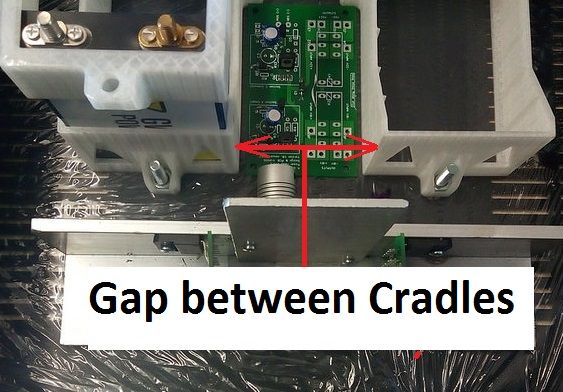
When you get a moment will you take a measurement between the 2 base cradles for the batteries like in the picture below.
I can then work out lengths for the struts and get some ready for the prototype build.
I need to get you 4 of the rod inter-connectors between tops and bottoms as well.
Re: It didn't explode....... YET (aka niges amp)
Posted: Wed Apr 26, 2017 4:39 pm
by Derek
Lads it's looking brilliant!
Sorry to read you were under the weather Nigel and glad you're back on track.
I feel a bit like a spare wheel but not as useful, if you need a dig out give me a shout.
Re: It didn't explode....... YET (aka niges amp)
Posted: Thu Apr 27, 2017 11:42 am
by nige2000
Sligolad wrote: ↑Wed Apr 26, 2017 2:12 pm
Nice work Nige, starting to look better than I had imagined now.
When you get a moment will you take a measurement between the 2 base cradles for the batteries like in the picture below.
I can then work out lengths for the struts and get some ready for the prototype build.
I need to get you 4 of the rod inter-connectors between tops and bottoms as well.
65mm
Re: It didn't explode....... YET (aka niges amp)
Posted: Wed May 03, 2017 12:20 am
by nige2000
these are the balanced battery charging cables
these are a real pain in the arse to make
ive heat shrink to go on them yet


